
Information
Advantages
★ Motor and driver wiring should be carried out in power-off condition, do not live wiring.
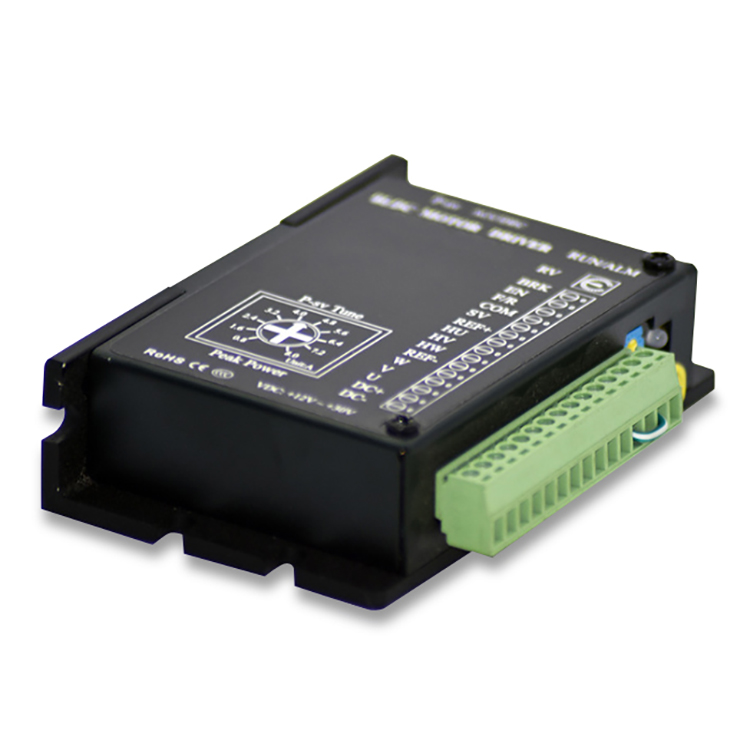
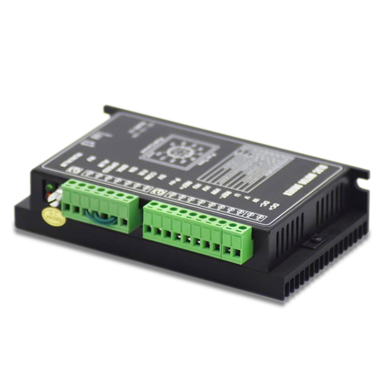
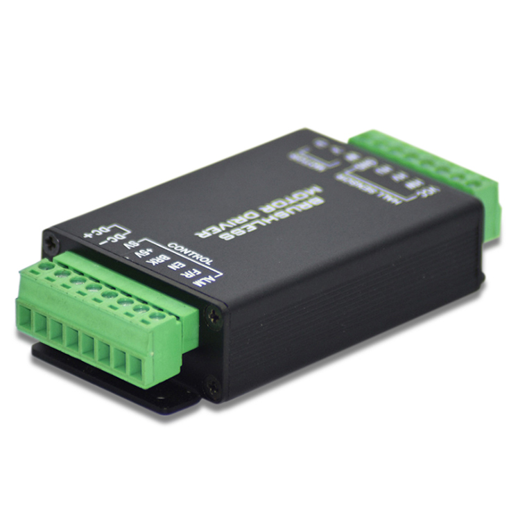
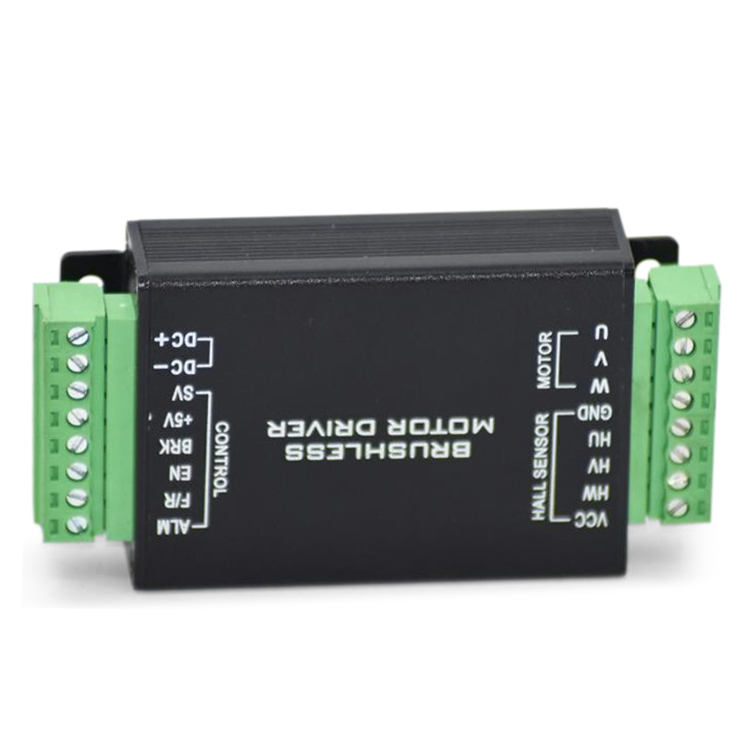
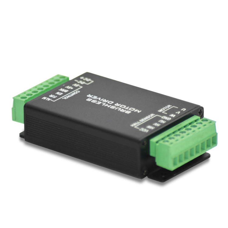
★Connect the power cord, motor winding wire and Hall signal line correctly according to the diagram method, note UVW the order of three phases must be consistent.
★ DO not disassemble the drive at will to prevent damage to the device.
★ Do not touch all terminals during operation.
★ No drive without enclosure.
★ impact drive may cause damage.
Motor Technical Data
| Electrical Specifications | ||||
| Projects | Minimum value | Typical values | Maximum value | Unit |
| Input voltage | 12 | 12 | 24 | VDC |
| Output current | 3 | 6 | 8 | A |
| undervoltage protection | 10 | VDC | ||
| Overpressure protection | 30 | VDC | ||
| Speed control | 150 | 3000 | 30000 | Rpm |
| Weight | 0.28kg | |||
| Size | 60*45*33 Unit MM | |||
| Control mode | Square waves | |||
| Speed regulation mode | 0-5 VDC analog input, 0-100% PWM input (PWM frequency range :[1 Kz-20KHz) | |||
| Over-current protection function | Overcurrent protection occurs when the current exceeds the operating current setting value and lasts a set time | |||
| Overpressure | An overvoltage protection occurs when the voltage exceeds 30 V | |||
| undervoltage | undervoltage protection when voltage is below 10 V | |||
| Hall anomaly | Hall signal anomaly | |||
| We can also customize products according to customer requirements. | ||||